A display module manufacturing line requires the application of various disciplines of engineering, from fundamental material science all the way to applied mechatronics. Before diving into the equipment and materials that are the beating heart of a module line, it’s important to understand the process that engineers envision feeding materials into and flowing partially- or fully-completed components out to subsequent steps.
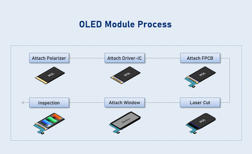
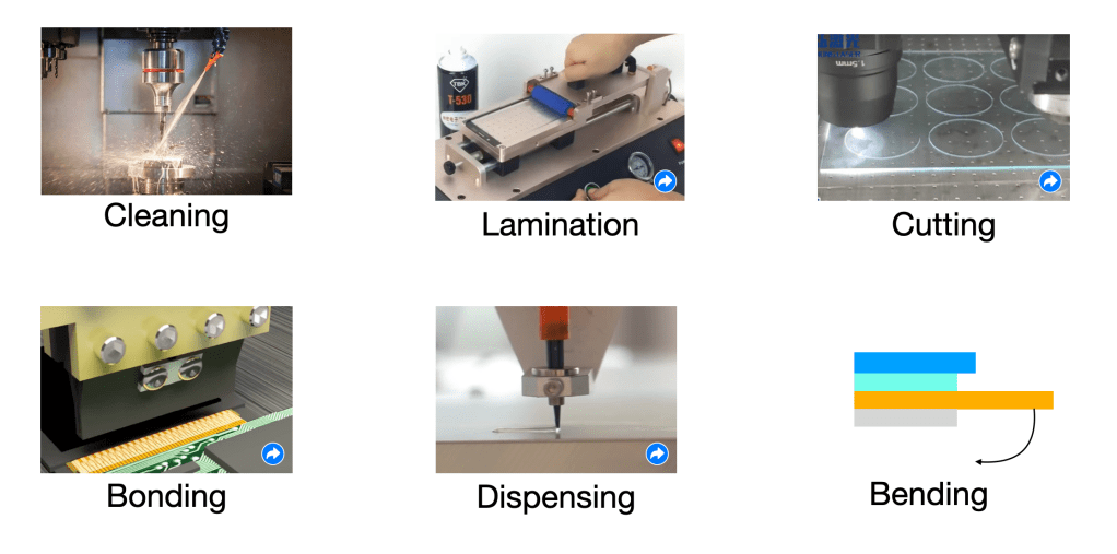
In general, we can imagine that a module process to cover a wide variety of activities based on new materials or designs that a product is trying to integrate – however, all of these unique items can be generally broken down to the following 6 processes:
- Cleaning – Removing contamination from key surfaces before further processing
- (De)Lamination – The removal or addition of a flat film to a flat surface
- Cutting – Excess material removal, generally to define the final form
- Bonding – Forming new permanent interfaces within the module, primarily for electrical connection
- Dispensing – Depositing a liquid to achieve geometry-constrained component addition
- Bending – Manipulating the ‘flat’ partial module into a 3D state more representative of final form factor
All of these processes have countless variations and unique challenges to solve, however they all must work together within a narrow process window to achieve a uniform part that is shipped to a downstream user such as a system integrator. One key aspect to remember for readers of our MCO insight is that all of these will be subject to their own in-process quality control (IPQC) metrics for both dimension (e.g. +/- 100um lamination accuracy) and specific process outcome (e.g. >95% cure ratio) – these are rarely defined by the equipment and material manufacturers, so a module engineer will need to be extra judicious in their application of new IPQC metrics and sampling quantities.
In the next posts we explore how the equipment and materials themselves are also important

Leave a comment