Today we finally break into the Meta Ray-Ban Displays, arguably the most polished version of heads-up display (HUD) glasses we have seen so far. Meta has opted to buck the trend for both the display panel and the waveguide, using a liquid crystal on silicon (LCOS) projector instead of the microLED versions we’ve seen in other brands, as well as a reflective waveguide that has some limitations on beam shaping, but is MUCH more efficient.
Fortunately I’ve learned how to wield my fat thumbs better than during the INMO teardown, so both our waveguide and projector survived unscathed after breaking open the faceplate – a very useful state for helping measure our projector. See the slightly more abbreviated video below for a complete review & explanation of the optics.
Projector-wise, Meta is using an LCOS panel from Omnivision, seemingly a modified version of the OP03011 that Omnivision has listed on their product page. This is a reflective display panel, which means that the image is not generated & emitted on the panel itself – instead, sequential frames of full blue, green and red shine on this panel, and the panel chooses which pixel to reflect to the user, or absorb in the projector, delivering 3-separate frames (blue, green, red) in rapid succession which then add to form the color image you see projected. See a visual example of what this means below:

When we measured Meta’s spectral output, we can see the individual LEDs that are the sources used for the reflected LCOS image – the LEDs are incredibly pure emitters, with FWHMs of ~20nm for blue and red, and ~30nm for green. This color purity is also maintained well through the waveguide which is reflective, therefore not adding too much noise through the diffractive elements that can sometimes reduce this purity – you can see just how much more narrow the color emission is vs. OLED in a head-to-head comparison of the Sony panel used in the Xreals below.
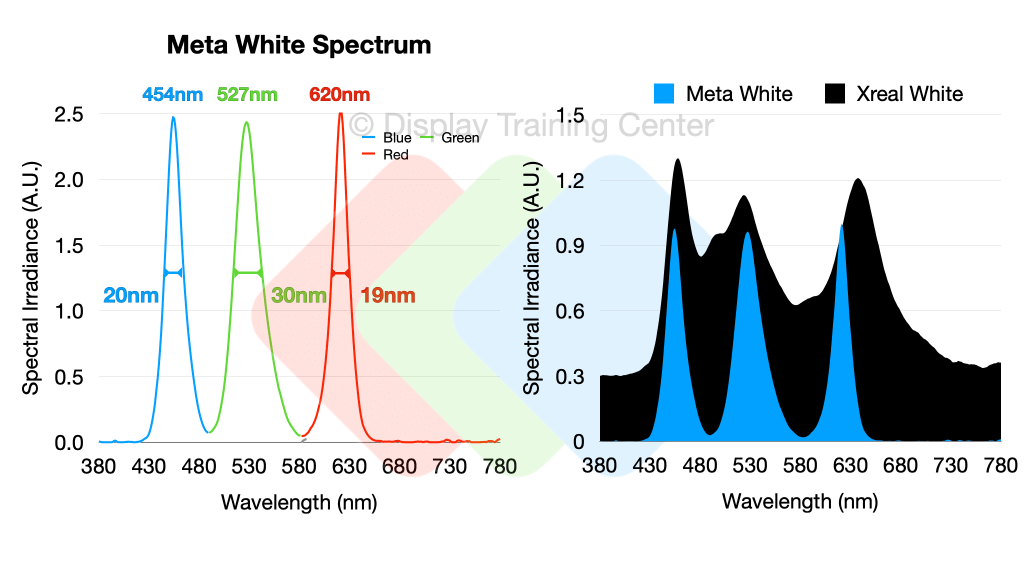
A pretty interesting find was that pure color emission is not all that pure when projecting just blue or green light – the red does still measure some small amount of blue and green channel, but I can’t be sure that this isn’t just the ghosts that can leak through the very complicated optical path (more on that later). Below you can see pure blue, green and red sent to the projector, and the mixed output that I’m sure is done intentionally so we don’t see an overly saturated image whenever we have full-color content.

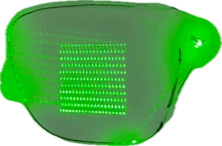
It’s probably important here to discuss a little about how the image itself is generated, and why we can get perceived color breakup both when looking at this display with significant head motion or when the display moves relative to a camera source, as was shown in the video with the captures below:

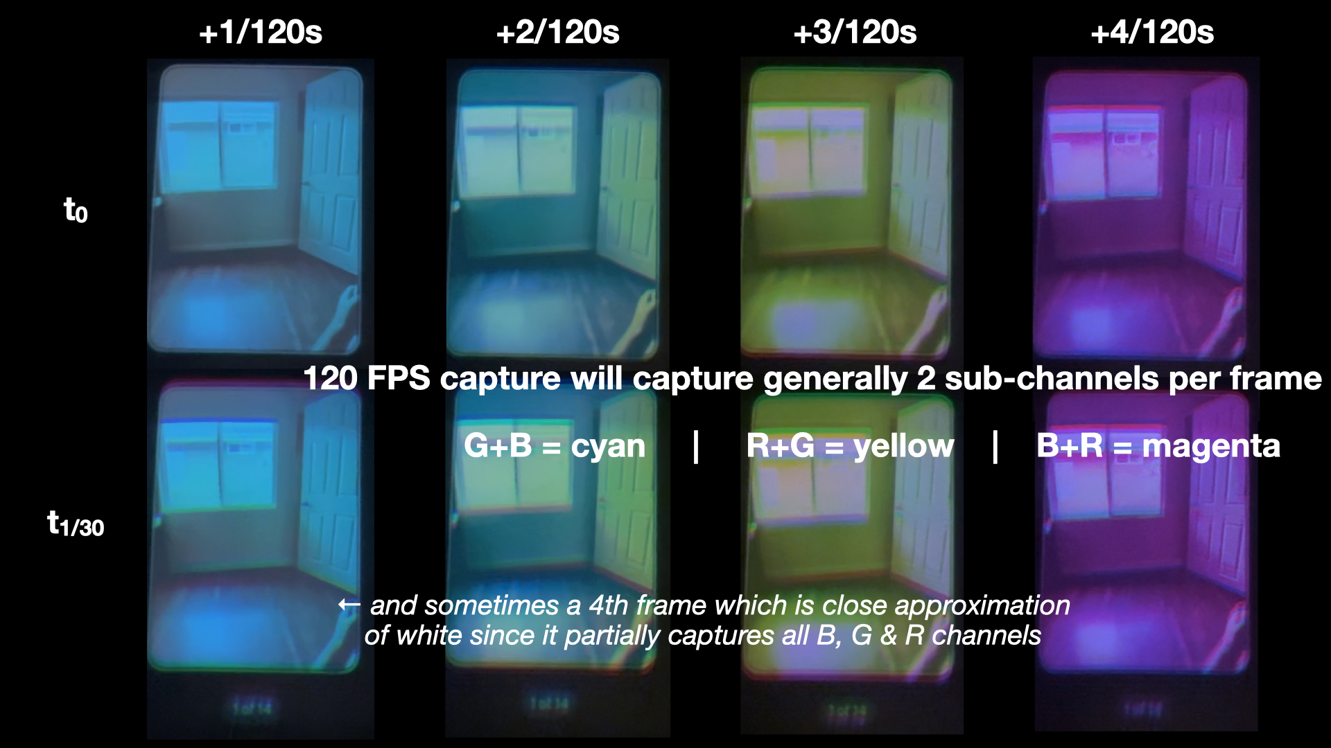
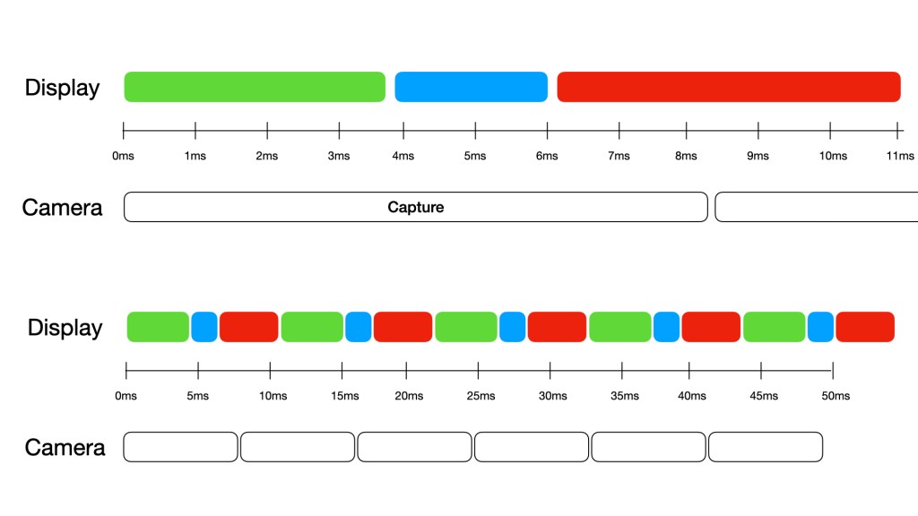
Essentially, the colors themselves are generated sequentially by strobing the individual blue, green, and red LEDs once every ~11ms – this light is then reflected off the LCOS panel (more on that later) which helps modulate the individual level of each color within each pixel, ultimately adding these three primary colors together within each pixel to form the target color… this works great for static situations like a projector on a wall or screen, but with some motion our eyes can detect one of these ‘sub-frames’ (either just the blue, green or red channel) in a different spatial coordinate due to the significant input lag between light emission from the display and the photostimulation of our color receptor cells. The reason we can partially capture these individual colors with a camera sometimes is due to short capture times (e.g. ~8.3ms for a 120Hz high-speed iPhone capture) – the timing diagram below shows how individual green, blue and red frames may be generated in an 11ms window, and how an 8.3ms capture will generally capture either 2 full color sub-frames plus a small amount of the third (creating yellow, cyan or magenta frames), or a little of all 3 colors creating a mostly full-color image. Complicated!
The geometric / reflective waveguide is complex, a bit too much so for a guy who just made glues during his industrial career to dig too far into… I recommend either Karl Guttag’s excellent in depth analyses over the years or Axel Wong’s recent review. There’s likely a bit more going on than the typical reflection we see through an input, expansion and exit grating (Axel references some patents that mention a mixing interlayer – time to break this apart more?), but in the meantime we can see the many reflective surfaces within the structure and how they bounce this green laser beam to the exit grating in the center of the waveguide. To me, this eyebox positioning is perfect (large frames) and I have little trouble seeing the entire 20° FoV at most positions.
Finally, I’ll wrap up with an optical path diagram from just the projector (still working on the waveguide…) As you may see just on the number of subcomponents alone, this is the most complicated display system we’ve seen so far by virtue of how many individual components have to be separately manufactured and precisely aligned & assembled… most others that use microOLED or microLED avoid many of these problems by having a directly emitting panel technology, and forces the heavy lifting to be done by the optics design. Thanks again to Karl Guttag for the continued discussions here and help on finalizing the diagram below.

Briefly, green light is emitted at a 90° angle to the red and blue sources (1), so they are combined via a dichroic mirror (2) which passes green, but reflects other wavelengths, therefore correctly angling all of our light along the primary optical path. The now ‘white source’ will go through a homogenizer known as a fly-eye homogenizer (3), essentially a mini-lens array which helps shape our beam into the specific square projection needed for the LCOS input. We then bounce off a 45° mirror (4) and enter a field lens = throughout which we’ve always been working with unpolarized light. Finally, as we get to our polarized beam splitter (PBS) we have to start working with polarized light, so we’ll have to pass through a linear polarizer (6) to enable the various reflections within the PBS. With linearly polarized light, we’re able to make the first bounce off the PBS (7) that will finally send light into the LCOS panel.
Before we get to the LCOS however, we go through one more lens (8) to help correct for any final distortions and aberrations once our image is generated. Finally we take our simple white source and generate an image on our LCOS panel (9) by modulating the individual liquid crystal pixels to be able to reflect varying amounts of light within each of our blue, green, and red channels. This is done by outputting light with a 90° rotation of polarization, which means on the path back through the PBS we will be able to pass through the element, priming us for the final bounce.
We need to change polarization state one more time, so the light enters a quarter wave plate (QWP – 10) to rotate our polarization state, and then bounce off a mirror (11), also mirroring our circular polarization state. This means that as we go through the QWP a second time, we actually return to a linear polarization that will bounce off our PBS, allowing us to finally project this image out of the projector. We’re not quite done here though, as there are two more optical elements to pass through before we exit the projector – some projection lenses (12) that serve to concentrate our projected image and an optical wedge (13) that will change the optical path slightly of our outgoing light to give it a shallower angle as we insert it into the waveguide.
And that’s it! For the projector at least… the waveguide (and associated lenses sandwiching it) are also complicated optical components that we’ll touch on a little later…

Leave a comment