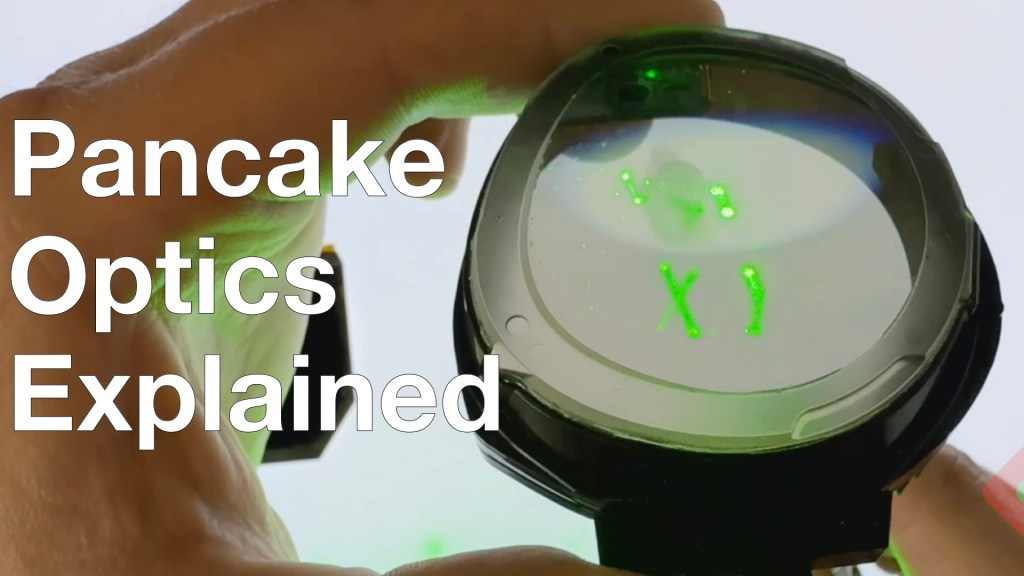
Only 2 years late to the party, we break into the Meta Quest 3 to see not necessarily the first application of pancake optics in a consumer device, but certainly the best value… Meta first introduced these optics in the Meta Quest Pro, but with a price 3x higher and a lower resolution display (but with full-array local dimming – we’ll chat about that another day) these didn’t really see mass adoption. Quest 3 is the first time a high-volume pancake optic made it into consumer hands, and it was time to dig into the design:
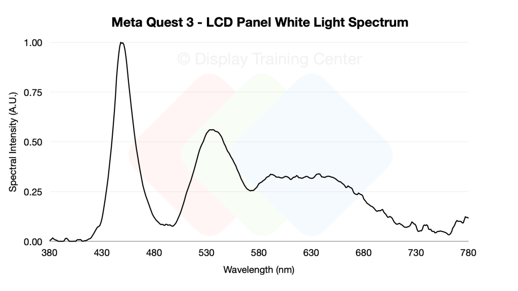
Display-wise, Meta is using a high-resolution LCD panel (reportedly from BOE and JDI), which you can very clearly see from the emission spectrum we get when showing white on the display. In the graph below, we see the tell-tale sign of a KSF-phosphor coated blue LED, which serves as the primary light source for our entire display. These LED’s are found in the backlight unit (BLU) we see in the video at 9:23 and inject phosphor-converted white light into the light guide plate, a piece of optical plastic that has been patterned with a series of dots that help extract light out into the LCD panel. We can see how the blue is still the strongest intensity peak here, with the green at ~50% of the emission peak, and red at ~30% – more importantly, we can see how the very narrow blue peak becomes much more diffuse when up-converting to the longer wavelengths
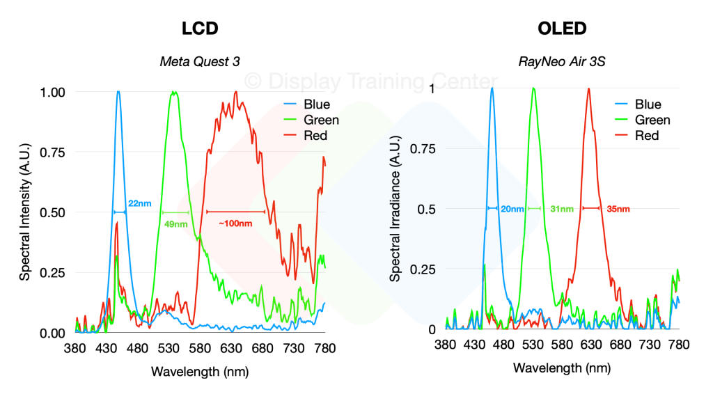
We can really easily see this when comparing the spectrum to an OLED panel – the blues are both quite narrow emitters (after all, the LCD is using a blue LED source to start…), but as we move to green and red the OLED panel maintains a similar color purity for these emitters, while the LCD’s color conversion means that we have a red emitter with a FWHM of 100nm!
Since we sacrificed one of our LCD panels and pancake optics to better understand the way light travels through our lenses, we can put together the optical path diagram below which outlines how light travels from our LED source (1) all the way to the user’s eye. You can easily follow the blue line to see how various LCD panel or lens elements interact with the light polarization, but briefly our light is emitted in a linear polarized state by the time it exits the top polarizer (5), which is the outermost layer of the LCD panel. From here, it will go into our lens optic which uses a half-mirror (6) for reflecting light once it’s inside the lens, passing through 2x QWPs (8, 9) to rotate the linear polarization 90° and then bouncing off our reflective polarizer (10). This allows the image to then travel through the lens 2 more times as it’s reflected back to the half mirror (b-path) and then back out to the user’s eye (c-path).
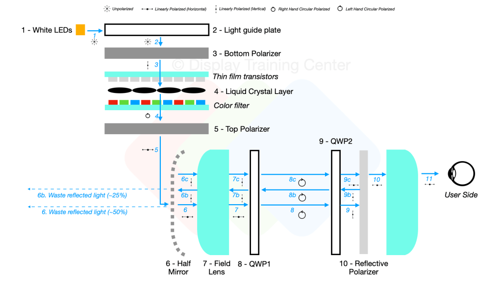
You’ll notice that there’s quite a bit of light lost through this process, mainly at the half mirror interface… upon first entry from the LCD panel, ~50% of the light will be reflected (due to space constraints, it shows a 90° bounce but really that light is going back into the LCD panel itself…) Then, once the image is bounced within the optic we lose another 25% of the light when bouncing the image back for the last time towards the user’s eye. Overall, more than 75% of the light in a pancake optic design is lost before reaching the eye – that’s why despite being able to start with very bright panels, most LCD-based VR headsets will be rated for ~100nits to the eye like the Quest 3.

Leave a comment